
Mike
Well-Known Member
This tech article was provided by rooster57.
Having 35 years in the industrial electrical trade and machine tool repair business doesn't make me an expert but it does help. I see a huge amount of questions in the electrical area so i hope this helps.
First and foremost when you are wiring your car decide up front what are you going to use for lights (std or halogen), horn ,electric fan (15AMP EBAY SPECIAL OR 30 AMP Spawn fan),tunes,tail lights 2 wire 3 wire LED std filament????, HEI internal external coil?? Gauges mechanical electric??? and so on . So the list is very important.
Next wire is not all the same. The insulation type is the difference in all stranded wire THHN, TFFN, THWN, TW, TWN, MTW and so on. SOLID wire should NEVER even be considered in a moving object. My preference is MTW for these type projects very tough the diameter if each wire is small and can be bundled to look quite nice. THHN, THWN, TFFN have a thermal plastic outer cover that can make it springy and difficult to bundle but not impossible and could be used if its all you have access to, This is the type of stranded wire you will find at lowes and home depot by the foot. The wire at like NAPA in the smaller rolls are a spin off of MTW.
Wire amperage this is the currant caring capacity the wire. A good rule of thumb is to use nothing smaller than AWG16 in the wiring of a car. I would only use 16 for signal circuits IE water temp sensor,electric gauge lights and fuel level signals and relay signals.
So lets talk about wire amperage and loads. A light bulb is a resistive load so a 50 watt load will not have any starting currant above its rating when its turned on. So that is to say it will not exceed the rated amperage IE 50 watts divided by the applied voltage of 12 volts is 2.27 amps so when you flip your switch to turn a resistive load on 2.27 is it( I know with a scope peak current can exceed the running current in any circuit but to simplify lets just say its negligible K ). But 30 amp fan motor however will have starting current. When the motor starts the spinning mass will need more currant until it gets up to speed. So this is how to calculate this 30amps times 125% minimum =37 amps so when the fan starts the wire that feeds it needs to be able to handle the load of 37 amps as does the relay and Molded plugs and connectors. So on fuel pumps,fan motors, and so on use the rated current times 125 % to rate the wire and relays.
Plugs and Connectors- Most molex and automotive weather-pack type connectors are rated in amperage. Don't assume because your wire will fit in the end of the connector its rating will support the applied load. Wire amperage, we can split hairs on the NEC version of wire amperage in a 30 70 deg or 90 deg Celsius environment so don't email me with my book says this and that. Simple is better here 6 amps and below AWG16 (6-15 amps AWG14) (15-20 amps AWG12) (20 to 30 amps AWG10) (30-40 amps AWG8) (40-50 amps AWG 6) if your calculation puts you right on the border go up a size its the safe thing to do.
Battery cables bigger is better my battery cable is 1/0. A lot of guys use welding cable for battery cables even though it will handle the currant the insulation (To soft) is not suitable for the positive cable but ok for the negative side if you don't have any choice.
Solder versus crimp connections. I like solder and heat shrink but only because of how the end result looks. The crimp connectors done properly work just as well.
Relays this seems to be a roadblock for some guys. So here is my take on the use of relays.Relay consists of a small amp draw 12 volt coil circuit when voltage is applied to the coil the relay contacts close sending voltage through its contacts to your device (cooling fan) at a much higher amperage.
I will use a relay to handle the load before I will let a manual switch do the work. They are much more durable and are designed to handle the load of what you are turning on. I use relays for horns, headlights, fans, fuel pumps. I will only use a switch including ignition switches for small loads. i can send you a drawing if needed
Wire support remember to use no metallic support for exposed wiring IE plastic tiewraps,insulated bolt-on straps,coil wrap,bulkhead connectors.
Fuses and circuit breakers This is personal preference, a fuse will blow and you need a new one to resolve the problem after the short is located and repaired. A circuit breaker only needs reset.
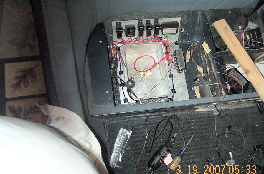
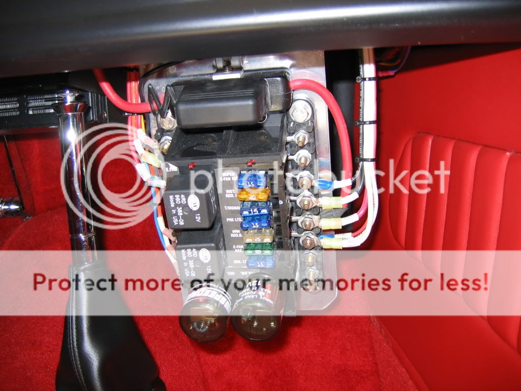
Fuse blocks and panels. Most fuse panels offered for cars IE Ron Francis,Easy-wire and so on can be overkill for these cars. The universal wiring kits can work well but often you only use half of what they send you. Building your own can be easy and look quite good when finished.
LED vs standard filament style bulb. The led type lamps are a current saving option but however they may need additional materials to make them work with standard flashers. LED flashers are available. I use the signal dynamics for my LED four-ways and turn-signals and its flawless.
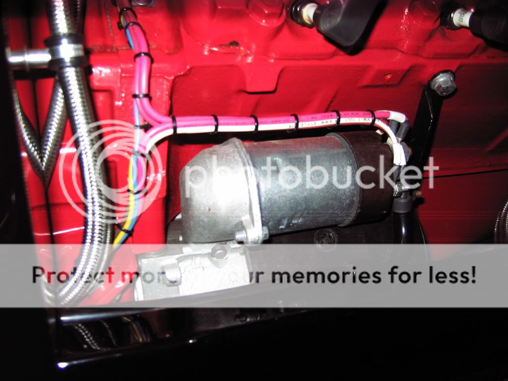
Voltage drop This is almost always the result of running to small a wire to a load like cooling fans, headlights (halogen),starter solenoids. So if your unsure of the current rating of something look on it and most times its written in some manner either in amperage or watts, If you only know the wattage of a device the amperage is found by dividing the wattage by the voltage if the circuit 12 volts. So a 150 watt headlamp divided by 12 volts is 12.5 amps times 2 because you have 2 headlights. The circuit total for wire and relay sizing would be 25 amps. This would be a standard size relay of 30 amps and AWG 10 for the wire size. IF IF you are feeding both headlights on one wire. Since each headlight is located on each side you could feed two 15 amp circuits one down each side of your car from that 30 amp relay fusing each headlamp at 15 amps at the relay location.
Parallel conductors -this is the use of two conductors in place of one large one. I do this when i have limited space bending radius or the connector wont accept the larger wire connector. DONT do this on wires smaller than number 10 (and yes i know the NEC has a standard of not smaller than number 4) My wire from the alternator is parallel AWG10 because my electric fan feeds directly from the alternator to a circuit breaker and a relay mounted on the radiator. The relay is powered from the temp sensor to turn the fan off and on so no wiring is needed from the inside of the car. This is my largest load so coming off the alternator is the best way in my opinion.
Solenoids they are related to a relay except they are designed to handle large loads. I use two solenoids one feeds the 12 volts to the entire fuse panel when its energized IE turn the key on and the fuse panel is hot and the other feeds power to the starter when the key is placed in the start position, by doing this when my key is off their is no power to anything on the entire car not even the starter solenoid.
AWG= american wire gauge
So this is my little bit of knowledge do with it what you will if you are a novice and need additional help email me and i will be glad to help you wire safely.
reach me at Rooster57@cox.net
Having 35 years in the industrial electrical trade and machine tool repair business doesn't make me an expert but it does help. I see a huge amount of questions in the electrical area so i hope this helps.
First and foremost when you are wiring your car decide up front what are you going to use for lights (std or halogen), horn ,electric fan (15AMP EBAY SPECIAL OR 30 AMP Spawn fan),tunes,tail lights 2 wire 3 wire LED std filament????, HEI internal external coil?? Gauges mechanical electric??? and so on . So the list is very important.
Next wire is not all the same. The insulation type is the difference in all stranded wire THHN, TFFN, THWN, TW, TWN, MTW and so on. SOLID wire should NEVER even be considered in a moving object. My preference is MTW for these type projects very tough the diameter if each wire is small and can be bundled to look quite nice. THHN, THWN, TFFN have a thermal plastic outer cover that can make it springy and difficult to bundle but not impossible and could be used if its all you have access to, This is the type of stranded wire you will find at lowes and home depot by the foot. The wire at like NAPA in the smaller rolls are a spin off of MTW.
Wire amperage this is the currant caring capacity the wire. A good rule of thumb is to use nothing smaller than AWG16 in the wiring of a car. I would only use 16 for signal circuits IE water temp sensor,electric gauge lights and fuel level signals and relay signals.
So lets talk about wire amperage and loads. A light bulb is a resistive load so a 50 watt load will not have any starting currant above its rating when its turned on. So that is to say it will not exceed the rated amperage IE 50 watts divided by the applied voltage of 12 volts is 2.27 amps so when you flip your switch to turn a resistive load on 2.27 is it( I know with a scope peak current can exceed the running current in any circuit but to simplify lets just say its negligible K ). But 30 amp fan motor however will have starting current. When the motor starts the spinning mass will need more currant until it gets up to speed. So this is how to calculate this 30amps times 125% minimum =37 amps so when the fan starts the wire that feeds it needs to be able to handle the load of 37 amps as does the relay and Molded plugs and connectors. So on fuel pumps,fan motors, and so on use the rated current times 125 % to rate the wire and relays.
Plugs and Connectors- Most molex and automotive weather-pack type connectors are rated in amperage. Don't assume because your wire will fit in the end of the connector its rating will support the applied load. Wire amperage, we can split hairs on the NEC version of wire amperage in a 30 70 deg or 90 deg Celsius environment so don't email me with my book says this and that. Simple is better here 6 amps and below AWG16 (6-15 amps AWG14) (15-20 amps AWG12) (20 to 30 amps AWG10) (30-40 amps AWG8) (40-50 amps AWG 6) if your calculation puts you right on the border go up a size its the safe thing to do.
Battery cables bigger is better my battery cable is 1/0. A lot of guys use welding cable for battery cables even though it will handle the currant the insulation (To soft) is not suitable for the positive cable but ok for the negative side if you don't have any choice.
Solder versus crimp connections. I like solder and heat shrink but only because of how the end result looks. The crimp connectors done properly work just as well.
Relays this seems to be a roadblock for some guys. So here is my take on the use of relays.Relay consists of a small amp draw 12 volt coil circuit when voltage is applied to the coil the relay contacts close sending voltage through its contacts to your device (cooling fan) at a much higher amperage.
I will use a relay to handle the load before I will let a manual switch do the work. They are much more durable and are designed to handle the load of what you are turning on. I use relays for horns, headlights, fans, fuel pumps. I will only use a switch including ignition switches for small loads. i can send you a drawing if needed
Wire support remember to use no metallic support for exposed wiring IE plastic tiewraps,insulated bolt-on straps,coil wrap,bulkhead connectors.
Fuses and circuit breakers This is personal preference, a fuse will blow and you need a new one to resolve the problem after the short is located and repaired. A circuit breaker only needs reset.
Fuse blocks and panels. Most fuse panels offered for cars IE Ron Francis,Easy-wire and so on can be overkill for these cars. The universal wiring kits can work well but often you only use half of what they send you. Building your own can be easy and look quite good when finished.
LED vs standard filament style bulb. The led type lamps are a current saving option but however they may need additional materials to make them work with standard flashers. LED flashers are available. I use the signal dynamics for my LED four-ways and turn-signals and its flawless.
Voltage drop This is almost always the result of running to small a wire to a load like cooling fans, headlights (halogen),starter solenoids. So if your unsure of the current rating of something look on it and most times its written in some manner either in amperage or watts, If you only know the wattage of a device the amperage is found by dividing the wattage by the voltage if the circuit 12 volts. So a 150 watt headlamp divided by 12 volts is 12.5 amps times 2 because you have 2 headlights. The circuit total for wire and relay sizing would be 25 amps. This would be a standard size relay of 30 amps and AWG 10 for the wire size. IF IF you are feeding both headlights on one wire. Since each headlight is located on each side you could feed two 15 amp circuits one down each side of your car from that 30 amp relay fusing each headlamp at 15 amps at the relay location.
Parallel conductors -this is the use of two conductors in place of one large one. I do this when i have limited space bending radius or the connector wont accept the larger wire connector. DONT do this on wires smaller than number 10 (and yes i know the NEC has a standard of not smaller than number 4) My wire from the alternator is parallel AWG10 because my electric fan feeds directly from the alternator to a circuit breaker and a relay mounted on the radiator. The relay is powered from the temp sensor to turn the fan off and on so no wiring is needed from the inside of the car. This is my largest load so coming off the alternator is the best way in my opinion.
Solenoids they are related to a relay except they are designed to handle large loads. I use two solenoids one feeds the 12 volts to the entire fuse panel when its energized IE turn the key on and the fuse panel is hot and the other feeds power to the starter when the key is placed in the start position, by doing this when my key is off their is no power to anything on the entire car not even the starter solenoid.
AWG= american wire gauge
So this is my little bit of knowledge do with it what you will if you are a novice and need additional help email me and i will be glad to help you wire safely.
reach me at Rooster57@cox.net
 wait till you have to trouble shoot something. There is a reason wires are color coded If you buy a kit each wire is usually labeled every few inches also to help find where each wire goes.Speaking of Zipties a gun is the best way to install these tightens and cuts it off.